


what is soak time
Understanding Soak Time in Environmental and Material Testing
A practical note for readers working with temperature-humidity chambers and material test methods.
Introduction
Soak time is one of those terms that appears simple until it is used in a specific laboratory or production context. In general, it refers to the period during which a material, component, or system is kept under defined conditions—such as temperature, humidity, pressure, liquid exposure, or mechanical load—long enough for an intended physical or chemical process to take place. The exact meaning therefore depends on the field. In manufacturing it may be called holding time; in material testing it may refer to immersion time, conditioning time, or equilibration time.
This article considers the term from the perspective of environmental testing and material evaluation. It does not attempt to provide a formal metrological definition. Instead, it explains how soak time is commonly understood in temperature-humidity testing and in material test programmes, and why the distinction between chamber conditions and sample conditions matters.
Soak time in temperature-humidity chambers
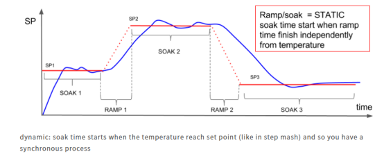
In a temperature-humidity chamber, soak time usually means the period for which a sample is exposed to the specified temperature and humidity after the chamber has reached the set conditions. The purpose is not simply to keep the chamber running. The purpose is to allow the sample itself to approach thermal and moisture equilibrium, so that the test condition is representative of the sample as a whole rather than only of the air surrounding it.
This distinction is important because the chamber air can reach the set value much faster than a solid sample, a packaged component, or a PCB assembly. Heat and moisture need time to penetrate the material. The required duration depends on the material, sample thickness, packaging, airflow, and sample placement. In some test standards, a soak or hold stage is also used to simulate a particular humidity condition or to expose time-dependent failure mechanisms. A sample may therefore need to remain under the specified conditions for hours or longer, depending on the test objective.
Soak time in material testing
In material testing, soak time often has a broader role. It may be a preconditioning step, an accelerated aging parameter, or an equilibration stage before mechanical testing. In moisture absorption studies, for example, researchers may calculate the soak time needed under accelerated conditions to produce a moisture content comparable to that obtained after long-term exposure in service. The calculation depends on the material and the assumed service environment, and the result should be treated as part of the test design rather than as a universal value.
Many standards also specify soak time explicitly so that different laboratories start from a comparable state. Geotextile tests may require immersion in water for a minimum period; liquid resistance tests on plastics may use different durations for short-term, standard, and long-term exposure; seawater tests may run for several weeks and may include wet-dry cycles. In high-temperature mechanical testing, a soak period may be used before loading so that the specimen reaches a uniform temperature. In each case, the purpose is to control the history of the sample before the measurement of interest.
Practical points to confirm
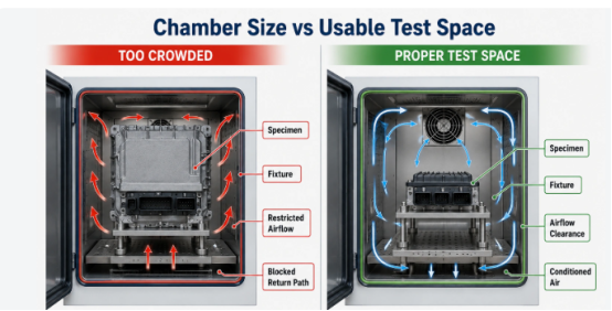
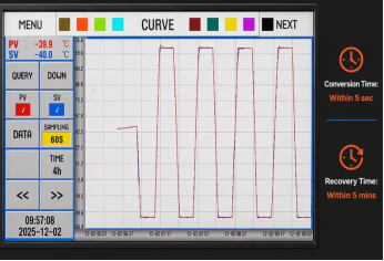
When soak time is used in a test plan, it is worth confirming what the clock is actually measuring. Does the soak time begin when the chamber display reaches the set point, or when a reference sample reaches equilibrium? Is the sample placed in a position where airflow and temperature distribution are representative? Does the standard define exposure time, holding time, recovery time, and conversion time separately? These questions may seem administrative, but they affect comparability and repeatability.
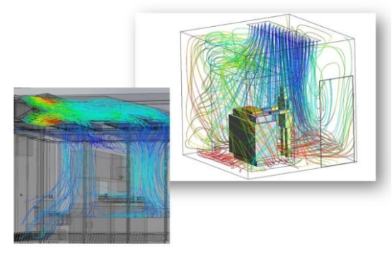
Different materials and products also have different requirements. Packaging materials, metals, plastics, semiconductor components, and PCBs may all be tested under thermal or humidity load, but the relevant soak time and acceptance criteria are not interchangeable. Equipment design—airflow direction, air velocity, temperature change rate, uniformity, and sensor placement—also influences the actual condition experienced by the sample. A test method should therefore be confirmed against the material, the sample size, the relevant standard, and the equipment performance.
Equipment specifications: a brief example
The following table is a simplified excerpt from an example specification list. It is included only to show the kind of information that may be relevant when selecting or comparing equipment. Full specifications should always be taken from the manufacturer’s datasheet and the actual configuration.
| Model | Internal dimensions (W×H×D, mm) | Weight (approx.) |
|---|---|---|
| TS-49 | 400 × 350 × 350 | 450 kg |
| TS-80 | 500 × 400 × 400 | 600 kg |
| TS-150 | 600 × 500 × 500 | 750 kg |
| TS-252 | 700 × 600 × 600 | 950 kg |
| TS-450 | 800 × 750 × 750 | 1200 kg |
Note: The example specification list also gives temperature range options of Type A: −40 °C to +150 °C; Type B: −55 °C to +150 °C; and Type C: −65 °C to +150 °C (200 °C optional). Control accuracy is stated as ±0.5 °C and uniformity as ±2 °C. These values are examples only and should be verified against the current specification.
Conclusion
Soak time is best understood as a controlled period of exposure that allows a sample or system to reach an intended state, or that subjects it to a defined environmental history. In temperature-humidity testing, it is closely associated with thermal and moisture equilibrium. In material testing, it may also serve as preconditioning, accelerated aging, or temperature equilibration. The exact duration is not universal; it depends on the material, the standard, the sample, and the equipment. For that reason, the most useful practice is to state clearly how soak time is defined in a given test and to distinguish between the condition of the chamber and the condition of the sample.
References
Washington State Department of Transportation. Materials Manual M 46-01 (Appendix D13) [PDF].
Available at: https://ftp.wsdot.wa.gov/contracts/9475-ChicoCreekandTributary-RemoveFishBarriersProject/ConformedRFP/ConformedAppendicies/Appendix_D/Appendix_D13_WSDOT_Materials%20Manual%20M%2046-01.pdf#82#99#82 (Accessed: 28 October 2026).
- لا شيء
- Asset Library